

What are MOSFETs afraid of?
Experience grows in proportion to the burned radio components. There is such a saying.
Well, there is another wise saying “A smart person learns from his mistakes, and a wise person learns from others” .
If all this is applied to radio electronics, then in order to avoid mistakes, we need to know what are the problem areas.
Let’s try to sort out one of the problems that almost all field effect transistors are subject to . And it doesn’t matter what power they are and what voltage they are .
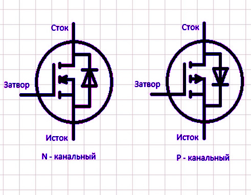
And this problem is related to the maximum voltage that can be applied to the gate of the transistor. And exceeded this allowable voltage, we will disable the transistor.
For example, let’s look at the characteristics of some popular transistor. For example IRFZ44
Features and Specifications
- Small signal N-channel MOSFET
- The continuous drain current (ID) is 49A at 25°C.
- The drain pulse current (ID-peak) is 160 A.
- The minimum gate threshold voltage (VGS-th) is 2V.
- The maximum gate threshold voltage (VGS-th) is 4V.
- Gate-source voltage (VGS) is ± 20 V (max.)
- The maximum drain-to-source voltage (VDS) is 55V.
- The rise and fall times are about 60 ns and 45 ns, respectively.
- It is commonly used with Arduino due to its low current threshold.
- Available in To-220 configuration
But in the context of this article. We will only be interested in the selected parameter — this is the Gate-Source voltage and this transistor has plus or minus 20 V.

If we look at higher voltage transistors. Their Gate-Source voltage is not much different. And usually a little more than 20 V.
And even if your useful signal does not exceed this voltage. It can be exceeded by various kinds of interference and interference that do not depend on you.
How to Protect MOSFETs
There is a solution to this problem and it is very simple. We will analyze three options for connecting protection.
1 Option:
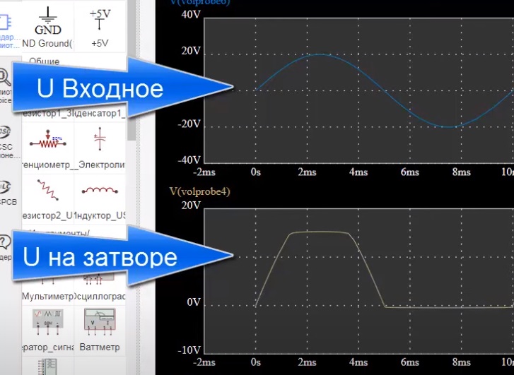
Use a simple 10 to 20 volt zener diode depending on the type of transistor and your input signal.

This scheme works. But she has a significant drawback. If both positive and negative gate voltage are important for your FET. Protection will limit the positive voltage not higher than that set by your zener diode and almost completely remove the negative signal.
This is clearly seen in the oscillogram below.
Option 2:
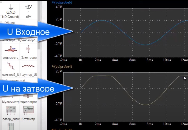
Let’s add another Diode to our protection circuit . It is advisable to use a Schottky diode.

As can be seen from the oscillogram, a signal of negative polarity appears at the gate of the transistor.
But such a scheme is recommended to be used only when you are sure that this voltage will not exceed the specified allowable threshold.
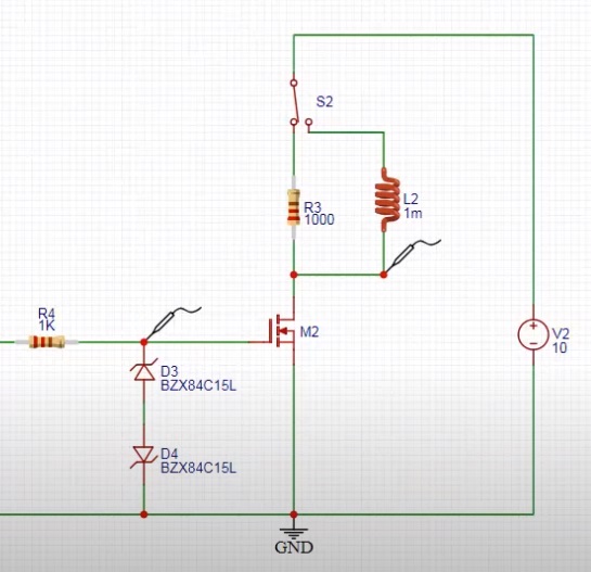
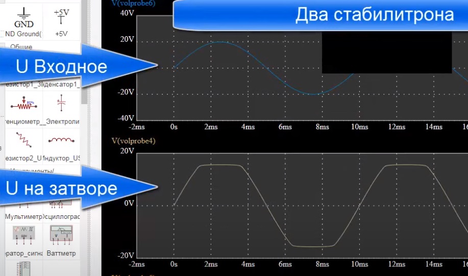
3 option:
The third version of the circuit does not have the disadvantage of the previous two circuits; it limits the signal of both positive and negative polarity.
Instead of two zener diodes, one bipolar zener diode can be used. Also suppressors work very well in this scheme . A In some cases, with high currents of impulse noise, they are even mandatory
As can be seen from the oscillogram presented below, the voltage is limited by plus and minus.
You can also use zener diodes for different voltages.
You can learn more about all this by watching the video below:
00:05 Introduction
00:23 What FETs are afraid of
02:09 The simplest protection scheme
02:51 Testing of the first protection scheme
04:05 Oscillograms
04:50 Second circuit test
06:00 The best protection scheme
06:38 Useful advice on the use of such a scheme
