

A small preface
This article is a continuation of the previous article . In which it was about a transistor amplifier and its OPERATING POINT.
There, the work of a classic amplifier on a single transistor was disassembled without any capacitors. There we figured out what principle a transistor amplifier works on and what depends on its operating point .

And, as many have pointed out. That in his base circuit, the resistor that supplies the bias to the base has a fairly low resistance. With what it can be connected?
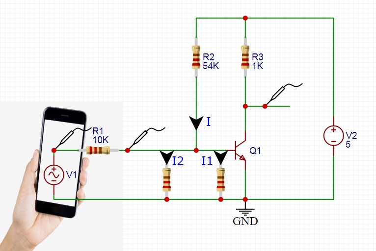
To do this, take a simple scheme. Which we have already used in the previous article. Let’s try to modernize it and figure out why this is happening.

And everything is very simple:
The one that flows through the resistor R2 is divided.
- One part flows through the PN junction of the Base-Emitter of our transistor . This is a useful Current for us. With which we set the bias voltage at the base and select the operating point of the Transistor.
- But there is also a second branch. Current flows through resistor R1 as well as the internal resistance of our signal source. If we had a circuit consisting of several stages. That would be the current flowing through the transistor of the previous stage.
You can find out more in the following video: https://youtu.be/wCjFPZ3kT3c
And since the PN junction of a transistor can also be represented as a resistance.
It turns out we have a divider. In the upper part of which there is one resistor R2. And in the lower part there are two resistors in parallel.
When connected in parallel, the total resistance decreases. And the total current flowing in this circuit increases.
This effect manifests itself — the operation of our amplifier begins to depend very much on the signal source that we use. Since each new signal source will shift our transistor operating point differently .
A simple solution to our problem CAPACITOR
We need to remove this dependency. There is a very simple solution to this — a capacitor .
We know that a capacitor passes a changing signal very well and is an obstacle to direct current.
To do this, we need to change the scheme a bit:

Add just one detail is the capacitor. Which will act as a separator. Also two appliances. With which we will measure the bias voltage, as well as the voltage of our operating point.
We did not change the rest of the scheme in any way. Completely taken from the previous article . And As you can see, with a given resistance of the base resistor of 54 kΩ, the bias voltage at the base has changed. And also our WORKING POINT has changed a lot. And the transistor went out of mode.
And that’s okay. The settings were made for the circuit without a coupling capacitor. When the bias of the transistor was influenced by the signal source.
Now picking up a new resistance. We will already know that the signal source no longer affects the mode of operation of our amplifier.
Replace the resistor R2 and you can test.

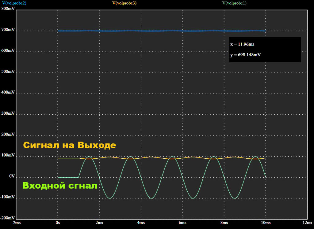
The working POINT of the Transistor is normal. And corresponds to about half the voltage of the power supply .

And as we can see from the waveform, our transistor operates in the mode. And there is no signal distortion.
Conclusions:
It remains only to look at the output signal to draw conclusions.
Thanks to the coupling capacitor, we removed the dependence of our amplifier on the internal resistance of the signal source.
