

PWM (pulse-width modulation) is a way to control the power supply to the load. The control consists in changing the pulse duration at a constant pulse repetition rate. Pulse width modulation is analog, digital, binary and ternary.
The use of pulse-width modulation makes it possible to increase the efficiency of electrical converters, especially for pulse converters, which today form the basis of secondary power supplies for various electronic devices. Flyback and forward single-cycle, push-pull and half-bridge, as well as bridge pulse converters are controlled today with the participation of PWM, this also applies to resonant converters.

Pulse-width modulation allows you to adjust the brightness of the backlight of liquid crystal displays of cell phones, smartphones, laptops. PWM is implemented in welding machines, in car inverters, in chargers, etc. Any charger today uses PWM in its operation.
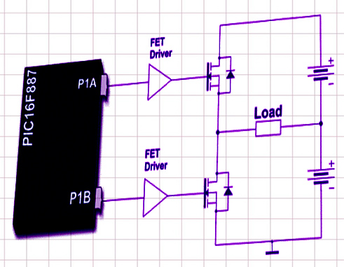
As switching elements, in modern high-frequency converters, bipolar and field-effect transistors are used, operating in a key mode. This means that the transistor is fully open for part of the period, and completely closed for part of the period.

And since in transient states lasting only tens of nanoseconds, the power released on the key is small compared to the switched power, the average power released as heat on the key turns out to be insignificant in the end. At the same time, in the closed state, the resistance of the transistor as a key is very small, and the voltage drop across it approaches zero.
In the open state, the conductivity of the transistor is close to zero, and the current through it practically does not flow. This allows you to create compact converters with high efficiency, that is, with low heat losses. And ZCS (zero-current-switching) resonant converters allow these losses to be minimized.
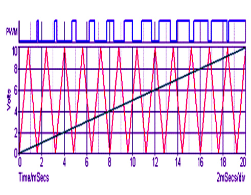
In analog-type PWM generators, the control signal is generated by an analog comparator when, for example, a triangular or sawtooth signal is applied to the inverting input of the comparator, and a modulating continuous signal is applied to the non-inverting input.
The output pulses are rectangular, their repetition rate is equal to the frequency of the saw (or triangular signal), and the duration of the positive part of the pulse is related to the time during which the level of the modulating constant signal applied to the non-inverting input of the comparator is higher than the level of the saw signal, which is fed to inverting input. When the saw voltage is higher than the modulating signal, the output will be the negative part of the pulse.
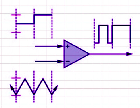
If the saw is applied to the non-inverting input of the comparator, and the modulating signal is applied to the inverting one, then the output square wave pulses will have a positive value when the saw voltage is higher than the value of the modulating signal applied to the inverting input, and negative when the saw voltage is lower than the modulating signal. An example of analog PWM generation is the TL494 chip, which is widely used today in the construction of switching power supplies.

Digital PWM are used in binary digital technology. The output pulses also take on only one of the two values (on or off), and the average output level approaches the desired one. Here, the sawtooth signal is obtained by using an N-bit counter. PWM digital devices also operate at a constant frequency, necessarily greater than the response time of the controlled device, an approach called oversampling. Between clock edges, the digital PWM output remains stable, either high or low, depending on the current state of the output of the digital comparator, which compares the signal levels on the counter and the approaching digital. The output is clocked as a sequence of pulses with states 1 and 0, each cycle the state may or may not change to the opposite. The frequency of the pulses is proportional to the level of the approaching signal, and units following each other can form one wider, longer pulse. The resulting pulses of variable width will be a multiple of the clock period, and the frequency will be equal to 1/2NT, where T is the clock period, N is the number of clock cycles. Here, a lower frequency is achievable in relation to the clock frequency. The described digital generation scheme is a one-bit or two-level PWM, pulse-coded PCM modulation.
![]()